

After breadboarding the AMZ Mosfet Booster, it’s time to finalize the design and assemble it.
Before going to finalize the design I do a short digression on what it means to have a transparent boost and what did that mean for me when choosing final list of components.
After this I go into settling for the final bill of material, then preparing the enclosure and finally soldering and assembling this pedal. At the end I’m going to try out this new creation.
Quick Digression on Transparent Boost
I was thinking about it after I finished breadboarding the effect, the booster was meant to be used as a transparent boost with as much headroom as possible. Transparent means that it does not colour the sound significantly, and from SPICE simulation I could see that the frequency response is flat, so the effect should not affect the sound … as far as the frequency response is concerned.
But from the transient analysis I could also see that some clipping might occur at highest gain. How and when the clipping occurs depends on transistor characteristics and biasing, and can cause some noticeable distortion of the signal.
Just as a reminder the circuit looks like this:

Since the point where the clipping occurs depends on the biasing (I can’t control the transistor characteristics) I could play around with setting the voltage at the point A (transistor’s drain voltage) as marked on the schematic, and get it to be inside the recommended range 4.5-5.5V. Per the effect’s page this can be done by changing resistance of the R2 resistor.
It is relatively simple, increasing R2 increases VA, and likewise, decreasing the resistance decreases VA.
Final List of Components
First of all, I decided to go with 2N7000. I was playing with it using a trim-pot to get it working and I liked the sound of it – but quite frankly, BS170 sounded just the same. I just spent more time playing with 2N7000 I guess.
As described above, I played around with getting VA to be around 5V (middle of the recommended range). When I checked the resistance on the trim-pot it said 38K, the closest I had was 43K and I went with that for R2. That puts VA at 5.3V. It is important to note that if I had chosen a different physical transistor I would have possibly chosen a different value for this resistor.
Adding all the paraphernalia to the schematic gives me the final diagram I’ll use for the assembly:

Oh, and not to forget. The pinouts for BS170 and 2N7000 are different so careful with that:

Final Bill of Material
I went through a great length on choosing components, so I’ll just list out components that I will use here.
| Designators | Component | Notes |
| 27969PSLA | Enclosure | |
| Protoboard | ElectroCookie board … spoiler alert: I butchered it later on. I had to cut it ☹ .. twice | |
| J3 | Cliff FC681473 | DC Power Socket |
| J1 | Switchcraft 112BX | In stereo Jack |
| J2 | Switchcraft 111X | Out mono Jack |
| R6 | 5K Linear Pot (P160KNP-0FC25B5K) | TT Electronics 5K linear pot |
| Knob | Knob that fits 6mm straight shaft – after cutting shaft to size | |
| S1 | SF17020F-0302-21R-L | Taiwan Alpha 3PDT latching foot switch |
| C1 | 1nF (0.001uF) | Metal film PET cap |
| C2 | 100nF (0.1uF) | Metal film PET cap |
| C3 | 10uF | Electrolytic cap |
| C4 | 47pF | Ceramic cap |
| C5, C6 | 100uF | Electrolytic cap |
| R1 | 100K | 1% 250mW metal film |
| R2 | 43K | |
| R3 | 10 Meg | |
| R4, R5 | 2.7 K | |
| R7 | 2.2 K | |
| D1 | 1N757A | 9.1 V zener diode |
| D2 | Led | 3mm Orange-Red, 2V forward voltage |
| Q1 | 2N7000 | MOSFET Transistor |
Preparing Enclosure
For drilling, I will just reuse drilling template I used the last time.

Here’s the template for convenience:
I’m getting lazy, but since I’m using pretty much the same components, I recon this will be fine.
I got some waterslide decal ink-jet paper so I decided to try out decal for decorating the box. Instructions are simple enough for me to follow, what could possibly go wrong?

Instructions 
Top Colour 
Prepping Paper 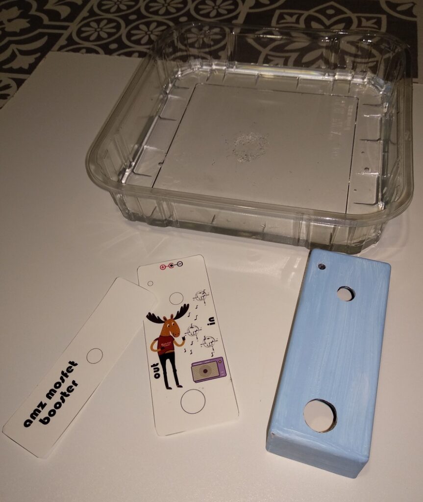


After applying the design 
Baking it
Similarly to how I painted my previous build I applied some primer and then, after the primer finished drying, I applied some acrylic paint with a brush to get that nice blue sky effect. Yep, that’s what I was totally going for.
After printing my design, I applied some clear, acrylic based varnish to seal it. After letting it dry, I cut out the design. The next step is to get the paper wet for a while so I can slide it onto the box.
The trickiest bit for me, doing it for the first time, is to slide the paper onto the box. Everything before that was easy. I got it smudged a bit unfortunately. The last step was to bake it – instructions say to do this for porcelain but I recon it will work just fine for aluminium as well.
Finally I applied some more varnish to give some extra protection to the design and the end result does not look too bad:
I think I had made several mistakes with this:
- I used cold water, instructions say – room temperature. I’m not sure how much of an effect that would have, but the paper did curl-up a bit while in the water – next time I’ll use water at room temperature
- I did not apply enough varnish, or I did not leave it dry for long enough. I’m guessing this is why I got some red-ish run-off from the paper – next time I’ll let it dry a bit longer
- I did not leave enough of the margin around the design so that made some of the edges bleed out, but again it could be just the previous issue – next time I’ll add some extra margin around the edges – instructions recommend 3mm
On my subsequent attempts, I had much better results with the above adjustments, but that’s for another time. I realized that I possibly did not soak the paper long enough too, since on subsequent tries I could slide it onto the box way easier by letting it soak just a tiny bit longer.
Anyway, the final result is good, nonetheless, I think.
Getting the Components to Fit
Ah, just like the last time, I had to do some cutting. It is the best if everything is pre-planned slightly better and components actually fit. Having said that – I use Farnell most of the time for ordering components. They have great same day dispatch service, but unfortunately they are not that great for their potentiometer selection.

Goes without saying that any of the cutting should be done with proper safety precautions. If cutting the protoboard, it is especially important not to inhale the fine dust that cutting it produces. It is really bed for the lungs.

Planning for Soldering
Following the final schematic I did a layout for this in DIY Layout Creator software:

Here’s the DIY Layout Creator file that I used for this:
Final Assembly
I’m ready now to solder everything:

As before, it’s good to test the effect before finally assembling everything:

Finally time to assemble everything and finish the pedal. Or it turns out not:

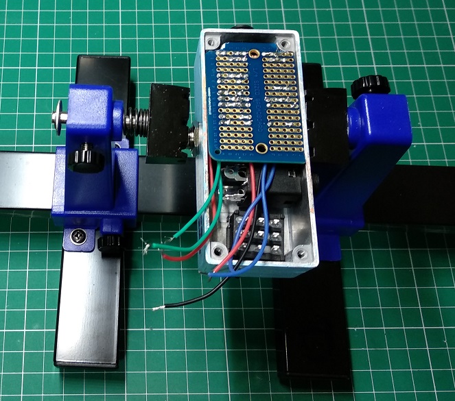
Maybe it does not show well on the photo, but the board cannot fit. Turns out I should’ve done proper planning instead of assuming it will fit based on my previous build.
If you notice I have some space between the output jack and the switch. That’s exactly how much I’m missing from the top of the box – I can’t place the board like this because it covers the screw holes and I can’t close the lid. If I had planned this properly I would’ve noticed this and moved the holes just enough towards the switch.
I can’t move the board towards the switch because components on the board would go over the jack, and that prevents me from putting the lid on. Time to take the Dremel out … again.
This just goes to show that preparation is half of the battle. Let’s move on.


Finally – the finished pedal:

Finished pedal 
With a knob 
And feet
Test Ride
Here is the pedal in action:


And a short video:
The pedal is very loud on last 20% of knob rotation. With the humbucker is just super loud. Very transparent, it has more treble compared to LPB I thought. All in all, success, despite my not so stellar planning (and truth be told, playing).